M3 Diesel Hybrid
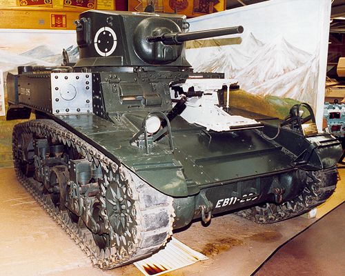
The vehicle in the following photographs is from the Bovington Tank Museum's collection and is displayed there as an M3A1. Externally the early M3A1 and M3 hybrids were identical, however, in it's current state this vehicle more closely resembles the internal configuration as found in a M3 Diesel Hybrid. I certainly wouldn't wish to suggest that the experts at Bovington have got this one wrong but for the purpose of this article we shall use this vehicle to highlight the essential features of an M3 Hybrid.
 |
© 1999 C. Shillito |
 |
© 1999 C. Shillito |
A criticism of the M3 was it's lack of a turret basket thereby forcing the gunner and commander 'walk' round with the turret when it was traversed. To address this a new turret was designed which, in addition to an integrated basket, eliminated the commander's cupola replacing it with a commander's periscope. A M6 37mm gun in the M23 combination mount was to be used and the turret incorporated hydraulic traverse. The tank to be fitted with this new turret was standardised as the M3A1 but in order to get these improvements into the field as quickly as possible the M3A 1 turret was introduced into the M3 production lines resulting in M3 hybrids. The vehicles had the new style turret but without the turret basket and hydraulic traverse (the equipment of which mounted on the basket floor). Not all the hybrids ended up with the same specification and indeed some had serious failings as we shall see later.
 |
© 1999 C. Shillito |
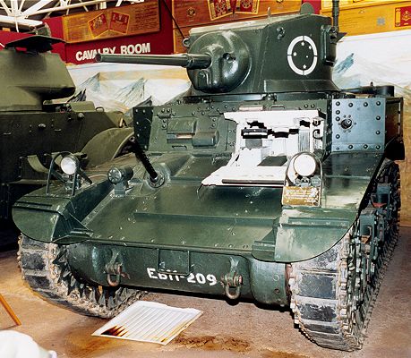
The 'horseshoe' turret of this vehicle, lack of cupola and the blanked off sponson machine gun port give the initial impression that this vehicle is a typical M3A1 and externally there is no real way of telling Hybrids from early production M3A1s. This 'hybrid' quite obviously has a riveted hull but there were no doubt examples that had the welded hulls of the late production M3s.
 |
© 1999 C. Shillito |
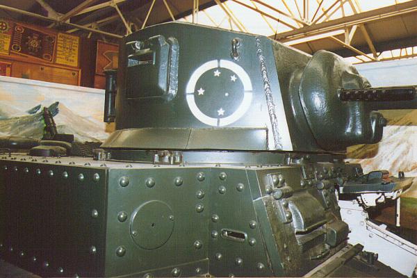
The vision flaps on the M3A1 style turret are mounted further up the turret wall than on the M3 as a consequence of the turret crew being positioned higher due to the turret basket. M3 Hybrids of course didn't have a turret basket and so these flaps may have been of little use other than for ventilation. In the Far East these flaps were often welded shut. Notice the prominent weld seam down the back of the turret showing that it is not, as one might assume, a single plate.
 |
© 1999 C. Shillito |
 |
© 1999 C. Shillito |
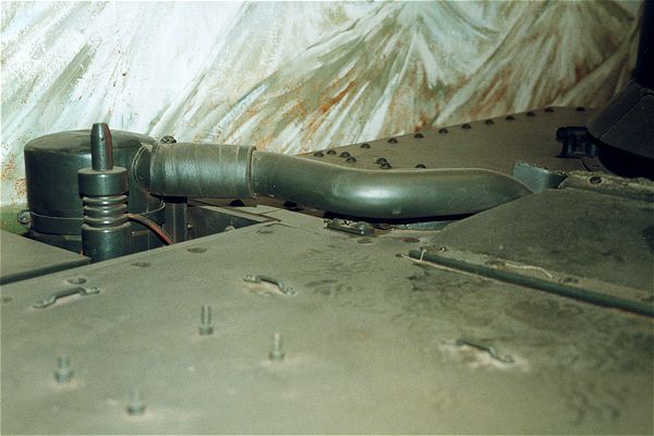
Inspection of the piping from the air intake filters at the rear of the vehicle reveals that this particular vehicle is a diesel. On gasoline tanks, the intake piping makes a right angle and disappears quickly into the engine compartment where as on diesel vehicles the piping trails across the engine deck. In total 4526 M3s were produced, most fitted with the W-670 gasoline engine, 1285 with the Guiberson T-1020-4 diesel engine. In British service the gasoline engine was by far the more prevalent with only 50 diesel engined tanks being exported to Britain. Note the aerial mount adjacent to the air cleaner.
Guiberson T-1020-4 Engine Specification
| Type | Radial, Air Cooled | Gross horse power | 245 at 2,200 r.p.m. | |
| Cylinders | 9 | Max. gross torque | 645 lb-ft at 1,300 r.p.m. | |
| Fuel | 40 Cetane Diesel | Crankshaft rotation | Counter clockwise | |
| Bore & Stroke | 5.125 in, 5.5 in | Length | 37 in | |
| Displacement | 1,021 cubic ins | Width | 45.5 in | |
| Compression | 14.5:1 | Height | 45.5 in | |
| Max. governed speed | 2,200 r.p.m. | Ignition | Compression | |
| Dry weight | 700 lb |
 |
© 1999 C. Shillito |
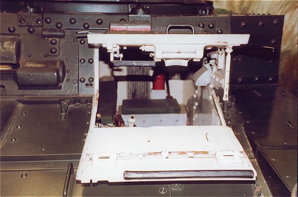
This glimpse through the driver's hatch shows that this vehicle does not have a turret basket and therefore is a M3 hybrid.
 |
© 1999 C. Shillito |
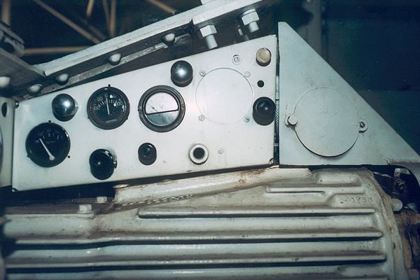
Compare this view of the driver's instruments for the diesel hybrid with those in the gasoline M3A1.
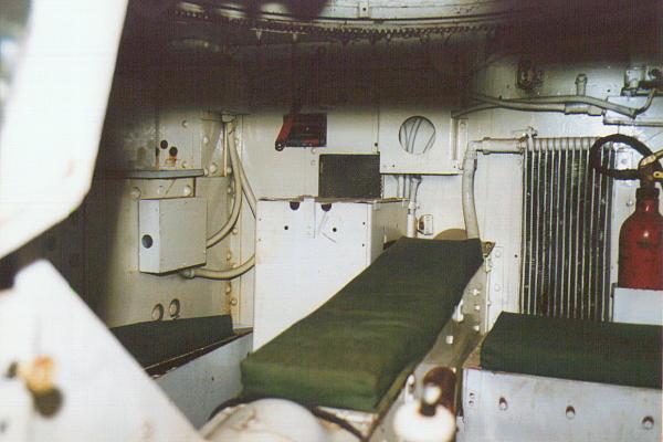
The dominant feature of these interior shots is the height of the drive shaft housing which angles down from the rear bulkhead dividing the fighting compartment into two. This height of this shaft is dictated by the upright mounting of the radial engine and subsequently accounted for the very shallow turret basket found on the later M3A1.
 |
© 1999 C. Shillito |
|
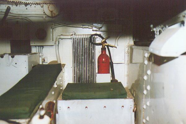
a | Transmission |
| b | 37mm Ammunition Box | |
| c | Filter | |
| d | Turret support roller | |
| e | Diesel engine cartridge starter | |
| f | transmission oil inlet | |
| g | Transmission oil cooler | |
| h | Fixed 10lb fire extinquisher | |
| i | 37mm ammunition box | |
| j | gear shift lever | |
| k | Drive shaft |
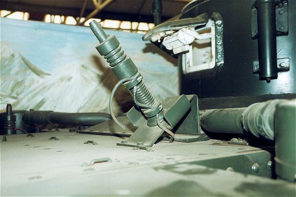
Mounted on the bulkhead we can see the device for firing the engine starter cartridges, a feature only applicable to diesel engined tanks.
 |
© 1999 C. Shillito |
 |
© 1999 C. Shillito |
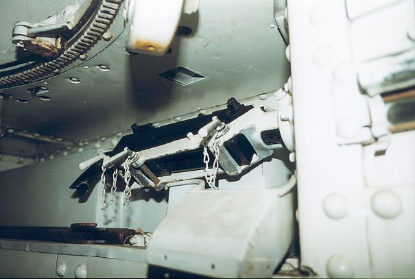
This photograph is looking at the left hand sponson where on this particular hybrid model we find, somewhat surprisingly, a sponson machine gun in it's mount. Whilst these machine guns were fitted as standard to the M3s they were 'officially' removed from the M3A1 specification (although I have seen photographs of Russian M3A1s fully equipped with sponson m.g.s). Hybrids, I would have thought would have been built to the M3A1 spec. with no sponson guns and blanking plates on their apertures. This vehicle is a real 'halfway house' with one sponson gun present and the other aperture plated over. Below the machine gun we can see the shute though which spent cartridges were ejected (presumably into a collection bag). On the hull ceiling we can see part of one of the three turret support rollers as well as the turret traverse lock .
 |
© 1999 C. Shillito |
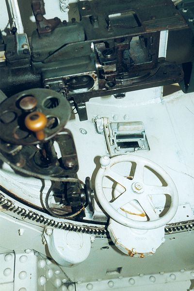
This photograph shows the gun mount inside the hybrid turret which whilst from the outside looks identical to an M3A1 turret, the interior layout owes much more to the M3. The large traversing wheel is mounted to the front right where as in a M3A1 the traverse was hydraulic with the traversing gearbox and hand crank located toward the rear of the turret. In the centre of the elevating wheel can be seen the firing button for the 37mm gun . The firing button for the coaxial machine gun is the black circular object to the left of the traversing wheel. This particular example does not have a linkage to the gunner's periscopic sight and indeed the sight itself is not present with the resulting aperture having been plated over. It may be that given the necessary traverse of the gun to achieve a fine lay, the sight linkage could not be fitted and so the only operative sight would be, as in the M3, the coaxial telescopic sight.
In the M3 the loader would initially lay the gun by manually cranking the turret, the controls for which were on his side. The gunner would then make fine adjustments by traversing the gun in its mount, which had a rack and pinion traverse of 20 degrees. However, on some hybrids the gun was locked in the mount and consequently the gunner had no means of laying the gun on target other than by shouting commands to the commander. On British tanks the manual traverse mechanism was sometimes re-located onto the gunners side giving him sole control which was more in line with British practice.